| Ford has offered factory installed "Upfitter Switches" in their
Superduty trucks since 2005. They are useful for installing
aftermarked lights, winches, power inverters, PTO equipment, and many other
creative uses. The switches are optional, so many trucks do not have
them from the factory. But for about $100, it is easy to install the
Ford OEM option in your own truck. The photographs here will cover
model years 2005-2007. |
| Enlarge Photo
These parts are available in kit form from many online sources, or you can visit your local Ford parts department and probably pay too much for the convenience. You will also need two 10-32 x 3/4" long screws. Hex heads work well if you can find them. |
|
|
|
|
Then pull your brake controller out. It just slides out, and is only held in place by friction. Reach a hand in from below to push from behind it. You may need to reach above it to push down on a spring-loaded ramp to get it moving. There are no fasteners, it just slides out. Note that the TBC needs to come out before the cubby can come out. Then remove the small plastic cubby hole by pinching it top to bottom and pulling out. It may be stubborn and you'll need to pinch hard. If you don't have the TBC, you'll just have a double wide cubby hole and it will come out in the same manner. |
While we are opening things up, remove the fuse panel access cover which is below the steering wheel on the drivers side. You'll find a photo of this a bit further down the page. |
|
|
Enlarge Photo
Fish the switch connector cable out through the hole where the switches will mount, and the rest of the cable will hang out of the fuse panel access cover under the steering wheel. Oops, I forgot to cover that - we'll get to it next. This completes our work on the passenger side, and now we have to work from the drivers side. You can replace the passenger side large glove compartment lid at this time. We're done on this side. |
 On
the drivers side, we should have already removed the passenger compartment
fuse panel access cover. I briefly mentioned it above. The panel
just pulls out at the top and hinges down, then pulls completely off.
It is laying on the floor of the truck in this photo.
There are 3 plastic clips at the top, so be careful not to lose them. On
the drivers side, we should have already removed the passenger compartment
fuse panel access cover. I briefly mentioned it above. The panel
just pulls out at the top and hinges down, then pulls completely off.
It is laying on the floor of the truck in this photo.
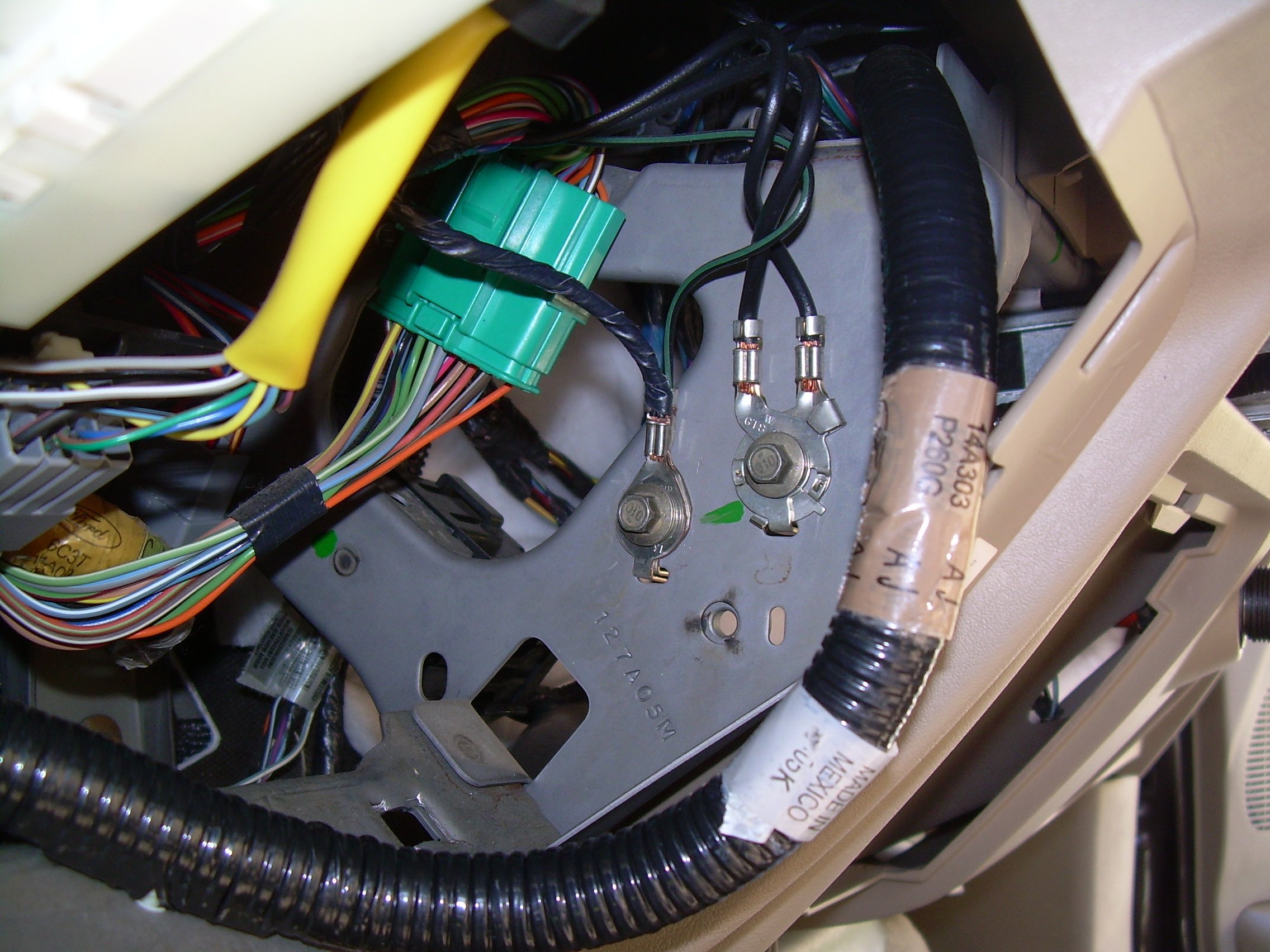
There are 3 plastic clips at the top, so be careful not to lose them.With the cover removed, there is plenty of space to fish the end of the cable out and let it hang as shown in the photo at left. Next, remove 4 bolts from the fuse block, and let it hang loose as well, also as shown in this photo. |
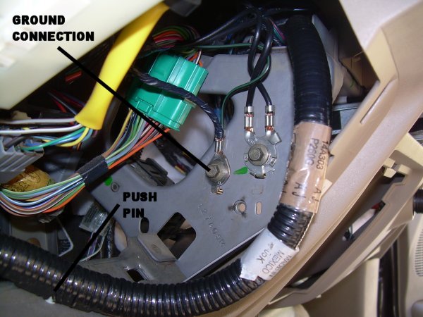 On
the right side of the opening, attach the harness ground using one of the
existing ground bolts. A good ground is essential, so make sure it is
tight. On
the right side of the opening, attach the harness ground using one of the
existing ground bolts. A good ground is essential, so make sure it is
tight.Then insert a push pin retainer as shown at left. The cable loop is sticking out of the opening here, but it will push back easily behind the opening when we button it up later. |
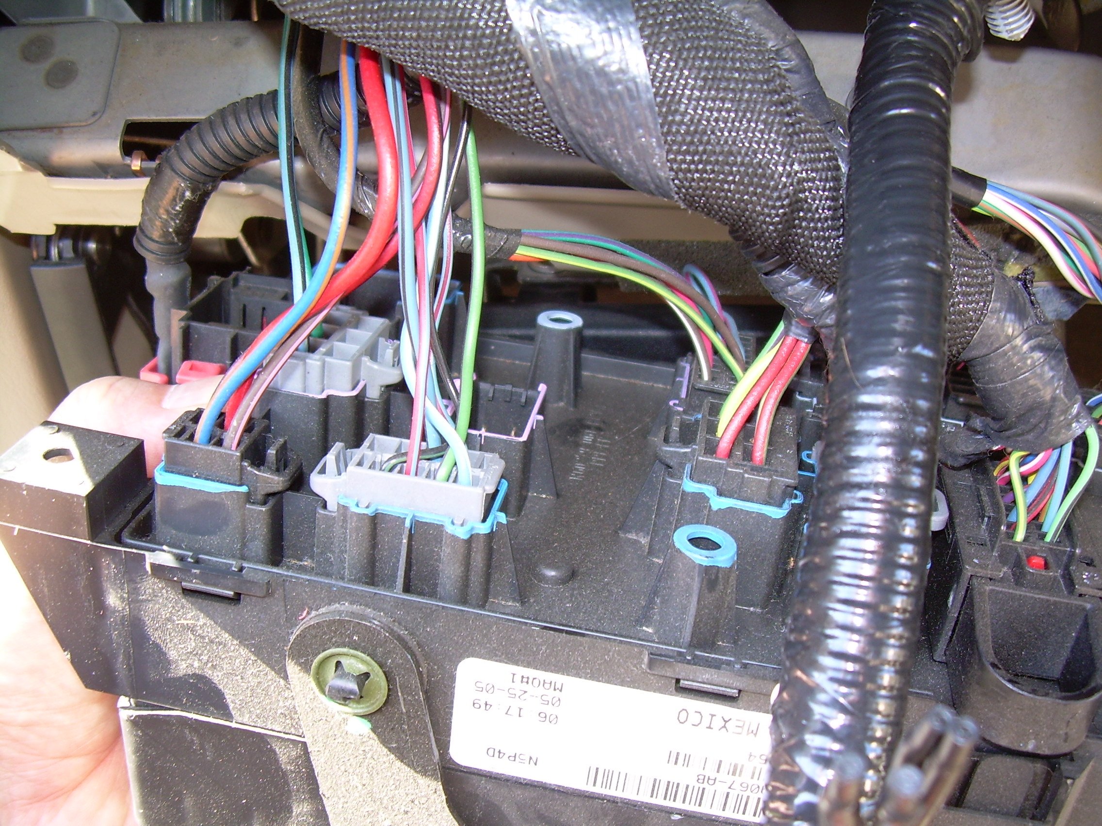
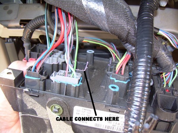 On
the back side of the fuse block you will find the empty socket for the
upfitter harness connection to the trucks power. Insert the connector
- it will only fit in one place, and it's keyed so you cannot get it wrong.. On
the back side of the fuse block you will find the empty socket for the
upfitter harness connection to the trucks power. Insert the connector
- it will only fit in one place, and it's keyed so you cannot get it wrong.. |
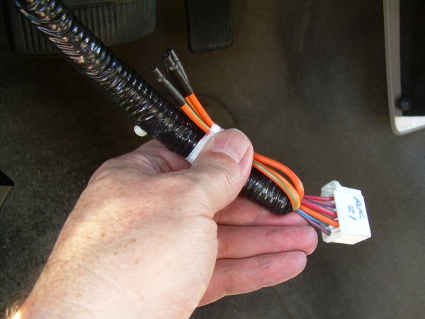 At
this point you can bolt the fuse block back in place. But before we
do, lets take a look at some details that will be required to actually use
the upfitter switches. At
this point you can bolt the fuse block back in place. But before we
do, lets take a look at some details that will be required to actually use
the upfitter switches.There are four flying leads (Ford calls them "Blunt Cut Wires" coming out of the connector which we attached in the previous step. Each of these wires is the output lead from the switches. The harness has a label which tells you which wire is for each switch. My thumb is covering the label in this photo. These are the wires to which you will connect whatever accessories you wish to control with the switches. |
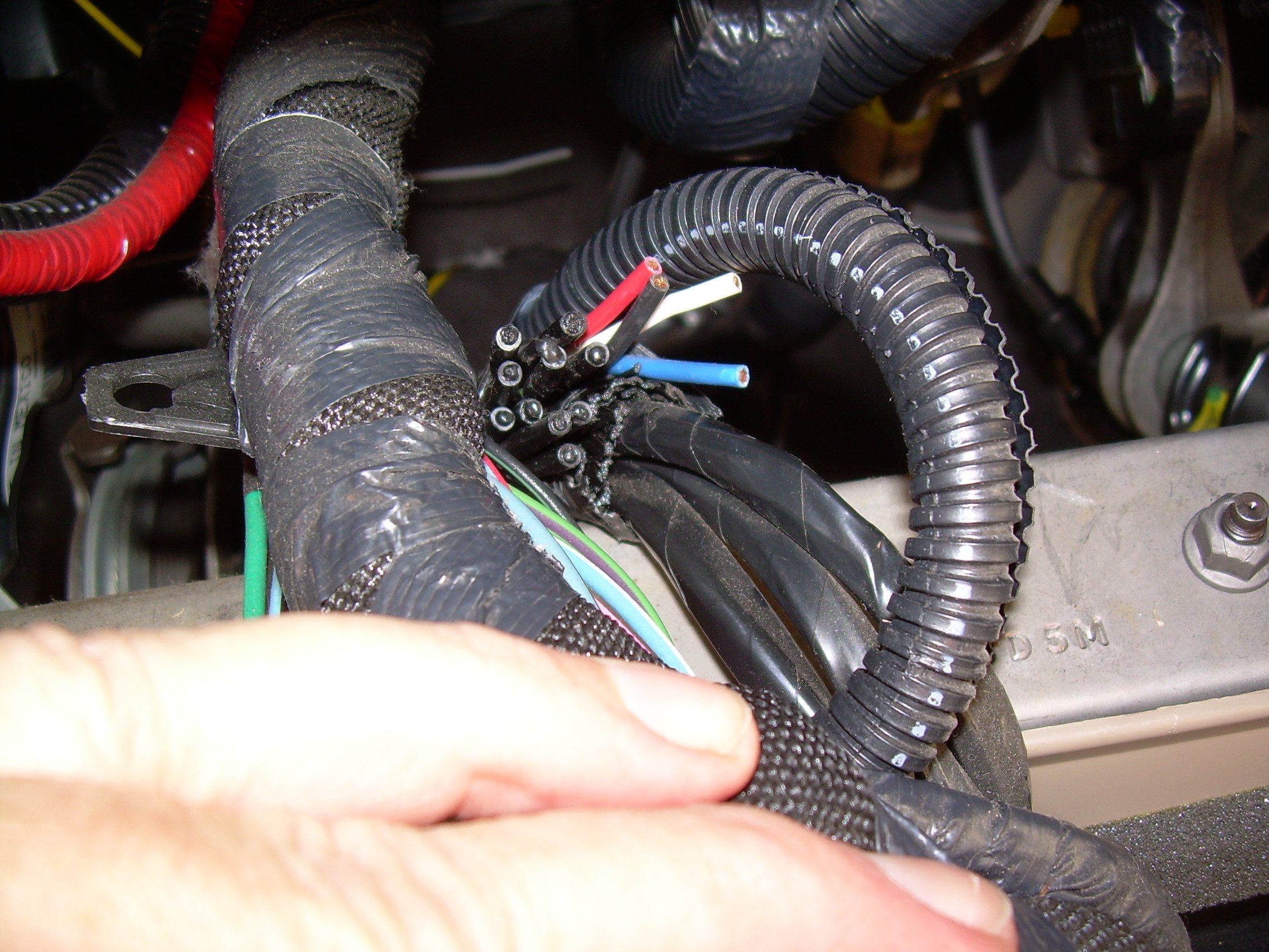
 In
the same area, behind the fuse block, you will find four bare cut wires.
They should be Black, Blue, Red, and White. If you open the engine
compartment of your truck, you should find these same wires on the firewall,
above the brake master cylinder, also with bare cut ends. Ford has
provided these wires for you to use any way you wish, and they already
penetrate the cab firewall, so they've made it really easy for us. You
can connect any one of these wires to an upfitter switch, and then connect
your accessory to the other end of the wire in the engine compartment. In
the same area, behind the fuse block, you will find four bare cut wires.
They should be Black, Blue, Red, and White. If you open the engine
compartment of your truck, you should find these same wires on the firewall,
above the brake master cylinder, also with bare cut ends. Ford has
provided these wires for you to use any way you wish, and they already
penetrate the cab firewall, so they've made it really easy for us. You
can connect any one of these wires to an upfitter switch, and then connect
your accessory to the other end of the wire in the engine compartment.Also contained in this bundle are leads which can be used to control functions built into your truck, such as Battery Charge Protect or PTO RPM control. I won't go into the details of how to use those functions, but at least you now know where to look for the wires. |
Replace all the trim components and we are done! Each switch has an LED indicator in the end of the stalk. It will light up whenever the switch is turned ON, whether there is actually anything connected to it or not. |
| Email me for comments and suggestions
|
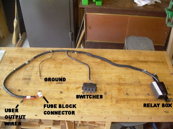 The
parts required are 1) a wiring harness with relay box, and 2) the upfitter
switch array (called "SWITCHES" in the photo at left. If you don't
have the factory trailer brake controller, you will also need a half size
cubby hole for the right side of the hole in your dash. If you have
the factory brake controller, the right side of the cubby is already
occupied by the brake controller.
The
parts required are 1) a wiring harness with relay box, and 2) the upfitter
switch array (called "SWITCHES" in the photo at left. If you don't
have the factory trailer brake controller, you will also need a half size
cubby hole for the right side of the hole in your dash. If you have
the factory brake controller, the right side of the cubby is already
occupied by the brake controller.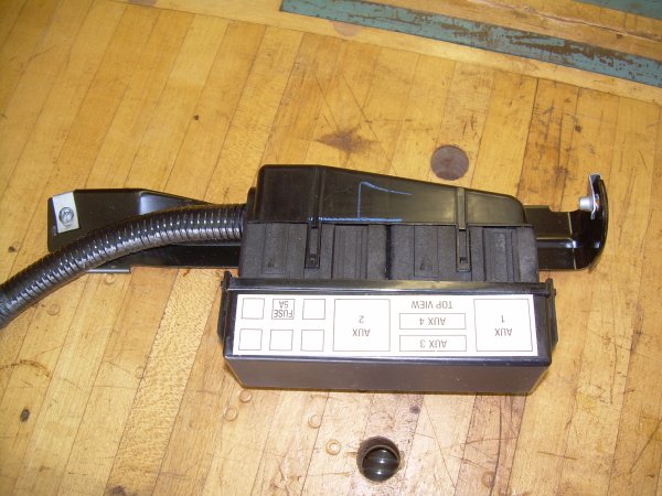 Here
is a closeup of the relay box and attached mounting bracket. This box
is going to mount above the passenger side large glove compartment with the
harness leading toward the drivers side. There will be a perfect
mounting location already present in your truck. The label on the box
will end up facing downward once it is mounted.
Here
is a closeup of the relay box and attached mounting bracket. This box
is going to mount above the passenger side large glove compartment with the
harness leading toward the drivers side. There will be a perfect
mounting location already present in your truck. The label on the box
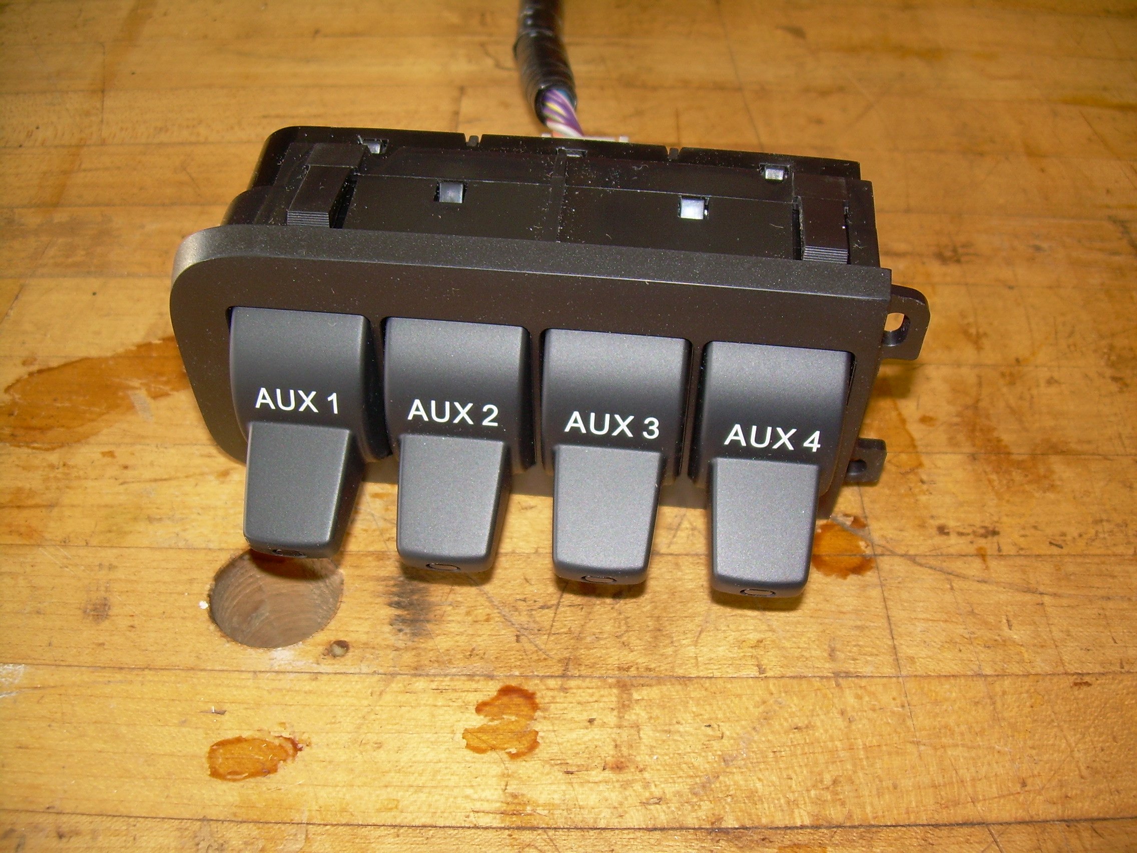
will end up facing downward once it is mounted.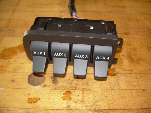 Here
is a closeup of the switch array. Notice there are no user accessible
wires on the switches themselves. All your output wiring will be done
behind the fuse block (we'll cover that below.) This switch array will
snap into the hole in your dash left when we remove the cubby hole.
Here
is a closeup of the switch array. Notice there are no user accessible
wires on the switches themselves. All your output wiring will be done
behind the fuse block (we'll cover that below.) This switch array will
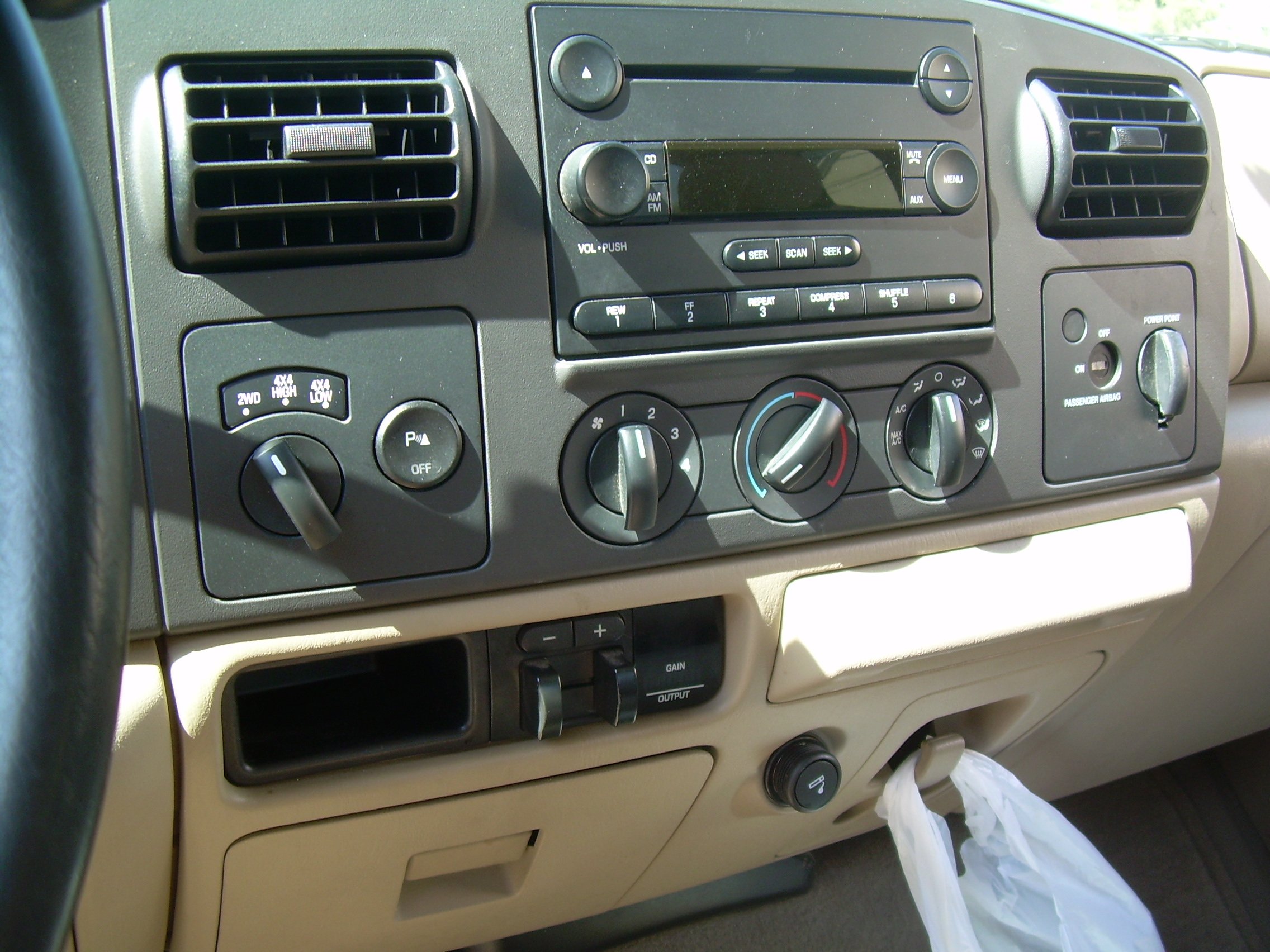
snap into the hole in your dash left when we remove the cubby hole. Here
is a shot of my dash before the retro-fit of the switches. Note my
factory trailer brake controller (TBC), and the half size cubby hole to its
left side.
Here
is a shot of my dash before the retro-fit of the switches. Note my
factory trailer brake controller (TBC), and the half size cubby hole to its
left side.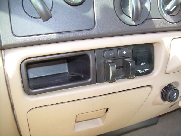 And
here is a closeup, just so we have our orientation crystal clear. Note
the driver side small glove compartment directly below the cubby/TBC.
Much of our work will be done through that opening.
And
here is a closeup, just so we have our orientation crystal clear. Note
the driver side small glove compartment directly below the cubby/TBC.
Much of our work will be done through that opening. Now
lets get started. Begin by lowering your drivers side glove
compartment all the way down. This is done by pinching the top of the
compartment together so that the two little rubber bumpers can pass through
the opening. Then just let it swing down. You can remove it if
you want, but it is not really necessary.
Now
lets get started. Begin by lowering your drivers side glove
compartment all the way down. This is done by pinching the top of the
compartment together so that the two little rubber bumpers can pass through
the opening. Then just let it swing down. You can remove it if
you want, but it is not really necessary.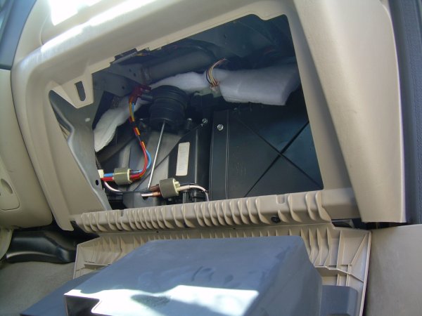 Now
we will open the passenger side large glove compartment. It swings out
just like the small one, by pinching the top together so the rubber bumper stops can pass through the opening. For this side I found it was a good
idea to completely remove the lid so that I could lay on the floor of the
truck to work. You can see one of the 3 screws that are to be removed
along the hinge of the lid in the photo at left.
Now
we will open the passenger side large glove compartment. It swings out
just like the small one, by pinching the top together so the rubber bumper stops can pass through the opening. For this side I found it was a good
idea to completely remove the lid so that I could lay on the floor of the
truck to work. You can see one of the 3 screws that are to be removed
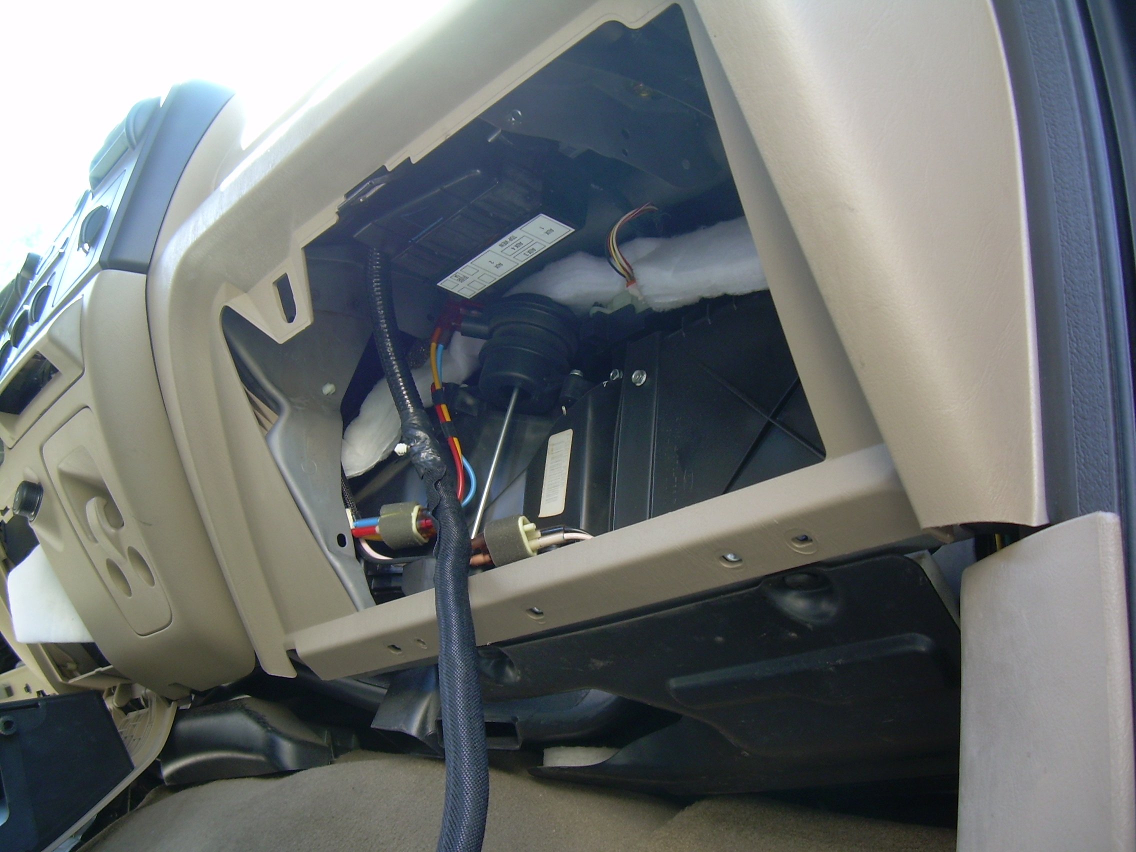
along the hinge of the lid in the photo at left.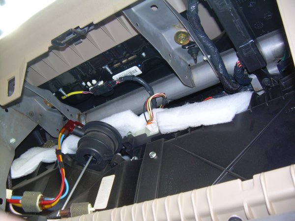 Here
is a closeup view looking up into the passenger side large glove compartment
box. This is looking at the bottom side of the dash, in the passenger
side air bag
area, and this is where our relay box must mount. The holes needed are
already provided, although you cannot tell which ones at this point.
Here
is a closeup view looking up into the passenger side large glove compartment
box. This is looking at the bottom side of the dash, in the passenger
side air bag
area, and this is where our relay box must mount. The holes needed are
already provided, although you cannot tell which ones at this point.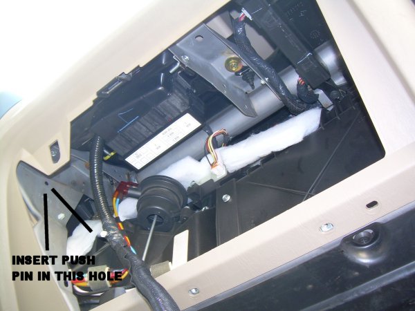 Here
is the same view, but now I have the relay box mounted in position. It
is mounted with two 10-32 screws, with the cable heading toward the drivers
side. Just leave the cable hanging down while you mount the relay box.
Here
is the same view, but now I have the relay box mounted in position. It
is mounted with two 10-32 screws, with the cable heading toward the drivers
side. Just leave the cable hanging down while you mount the relay box.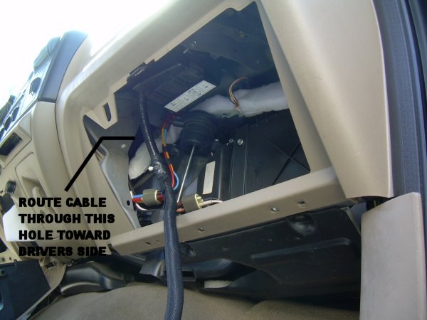 Bend
the cable in a loop, and insert the first push pin into the hole shown in
the photo above. Then fish the cable toward the drivers side.
Try to find the appropriate holes for the remaining push pins as you go, but
to be honest I'm sure I did not get them all correct. Just be sure
that the cable is secure and that it won't interfere with your cup holder
side, heater controls, etc. I found it helpful to remove the trash bag
holder clip to better see what I was doing. Just two screws are
removed and the clip comes right out.
Bend
the cable in a loop, and insert the first push pin into the hole shown in
the photo above. Then fish the cable toward the drivers side.
Try to find the appropriate holes for the remaining push pins as you go, but
to be honest I'm sure I did not get them all correct. Just be sure
that the cable is secure and that it won't interfere with your cup holder
side, heater controls, etc. I found it helpful to remove the trash bag
holder clip to better see what I was doing. Just two screws are
removed and the clip comes right out.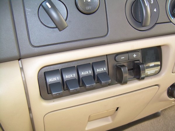 All
that's left now is to button it all up. The switches are the last
thing to connect. Just plug them into the harness that we left hanging
out through the hole. Then the switch array pushes straight into the
hole and snaps in place. Lastly push the TBC into place, or if you
don't have a TBC then push the new half cubby into
place.
All
that's left now is to button it all up. The switches are the last
thing to connect. Just plug them into the harness that we left hanging
out through the hole. Then the switch array pushes straight into the
hole and snaps in place. Lastly push the TBC into place, or if you
don't have a TBC then push the new half cubby into
place.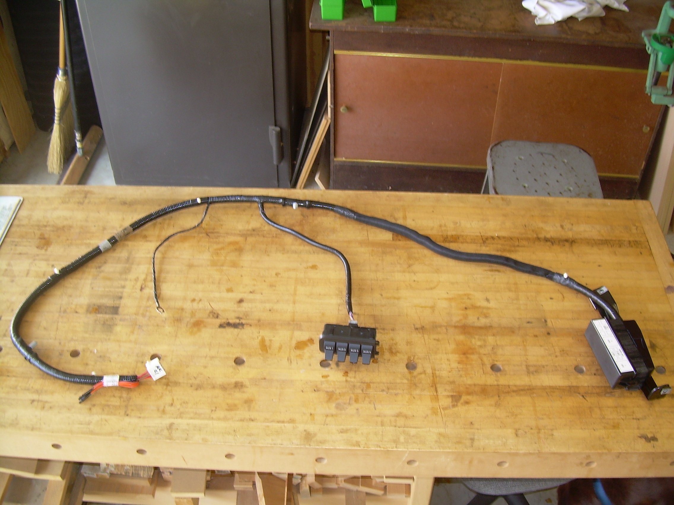